Trumpeter Seawolf Conversion Kit Instructions

The USS Seawolf, SSN 21, is an American Navy submarine, and is the lead ship in a class of 3 boats.  She is 353 ft long, has a 40 ft beam, and 937 tons submerged displacement.  In typical US Navy understatement of capabilities, she can sail at 25+ knots and dive to depths of “greater than 800 ft”.  Seawolf has 8 weapons tubes 26” in diameter and capacity for 50 reloads. With a design focus on extreme quietness at speed, Seawolf is said to be quieter running at 25 knots than a Los Angeles class sub sitting pier side. Seawolf was launched 24 June, 1995 and commissioned 19 July 1997. 

So, let’s start by taking a look at the Trumpeter model kit.

The artwork on the box is a nice depiction of Seawolf underway.  Inside we find the hull centre section in 2 pieces, and 3 spruces of parts.  The hull winds up being comprised of 6 pieces, 3 upper and 3 lower.  The spruces contain all the required parts for the dive planes and rudders, sail, propulsor, and even a nice stand.  The castings are all sharp with minimal flash. By itself it would build into a fine static model. But of course, you have other plans.

The R&R Engineering conversion kit has been designed to make the conversion simple for the first time submarine builder. It consists of a pre-assembled watertight compartment including drive components, ballast tank and pump system, and battery compartment all ready to be installed in the hull.From left to right in the following pic is the front end cap, battery and electronics section, ballast tank with baffles, pump and motor compartment, and rear end cap.

Let’s look at each of the sections.

Here we see the electronics and battery compartment. The lower part of the compartment has a support section sized for a standard 6 cell, 7.2 volt Ni MH or Ni Cad battery pack.It’s made to be quite easy to swap batteries and keep running the boat for as long as you wish.The top plate is flat and offers plenty of room for speed controllers, pitch controller, and radio receiver.

In the centre of the tube is the ballast tank, complete with baffles, inlet and outlet, and a central pass through tube for running the necessary wiring from the forward section to the aft section.

At the rear of the tube we find the pump and motor compartment. From left to right we see the reversible pump for the ballast tank, with the tubing from the inlet to the tank already installed. Above it we see the vent tubing from the top of the ballast tank run to the aft end cap fitting. Behind the pump is the drive motor already fully installed with a universal joint and drive shaft. Straddling the motor are a pair of 9 gram servos, again already fitted and the wires run thru the ballast tank to the forward compartment. Above the motor is fitted a latching on/off switch for the main power lead.

Here we see the aft end cap, and everything which comes through it. From the top there is a push button for the on/off switch, 2 push rods for the dive plane and rudder controls, and the main driveshaft with a yoke type arrangement to transmit rotation to the propeller shaft.  All of these are run through o-ring type seals with adjustable caps for the sealing pressure. Also here are the ballast tank vent fitting at the top, and the ballast water inlet fitting at the bottom.

As you can see, the amount of pre-fabrication and assembly make this entire unit a breeze to build.

Shown here is the tubing to attach to the ballast tank vent with the check valve installed.

Included with the conversion kit are also a number of components required for the transformation.  From the top we see a lovely pre built bulkhead with prop shaft bushing and bell crank for the dive plane linkages. Below that are the dive plane pushrods, cylinder end stop locators, cylinder “saddles”, and a set of bow reinforcements with magnets installed to hold the top and bottom of the hull together.  Off to the left side is the rudder pushrod, the prop shaft, and a pair of magnetic pushrod couplings.If you haven’t noticed yet, this entire unit is designed to be able to be removed from the hull with no tools or disassembly.

.Here’s a closeup of the prop shaft bearing / bell crank bulkhead.

Included also are a complete set of cast resin control surfaces with pivot shafts cast into position, a pair of lead-in fairings for the dive planes, and a carrier with a central bearing for the prop shaft. 

Also included in the kit are a full set of cast brass control arms, rudder yoke, prop shaft coupling and propeller.  These are drilled, tapped, and have stainless steel setscrews already installed.

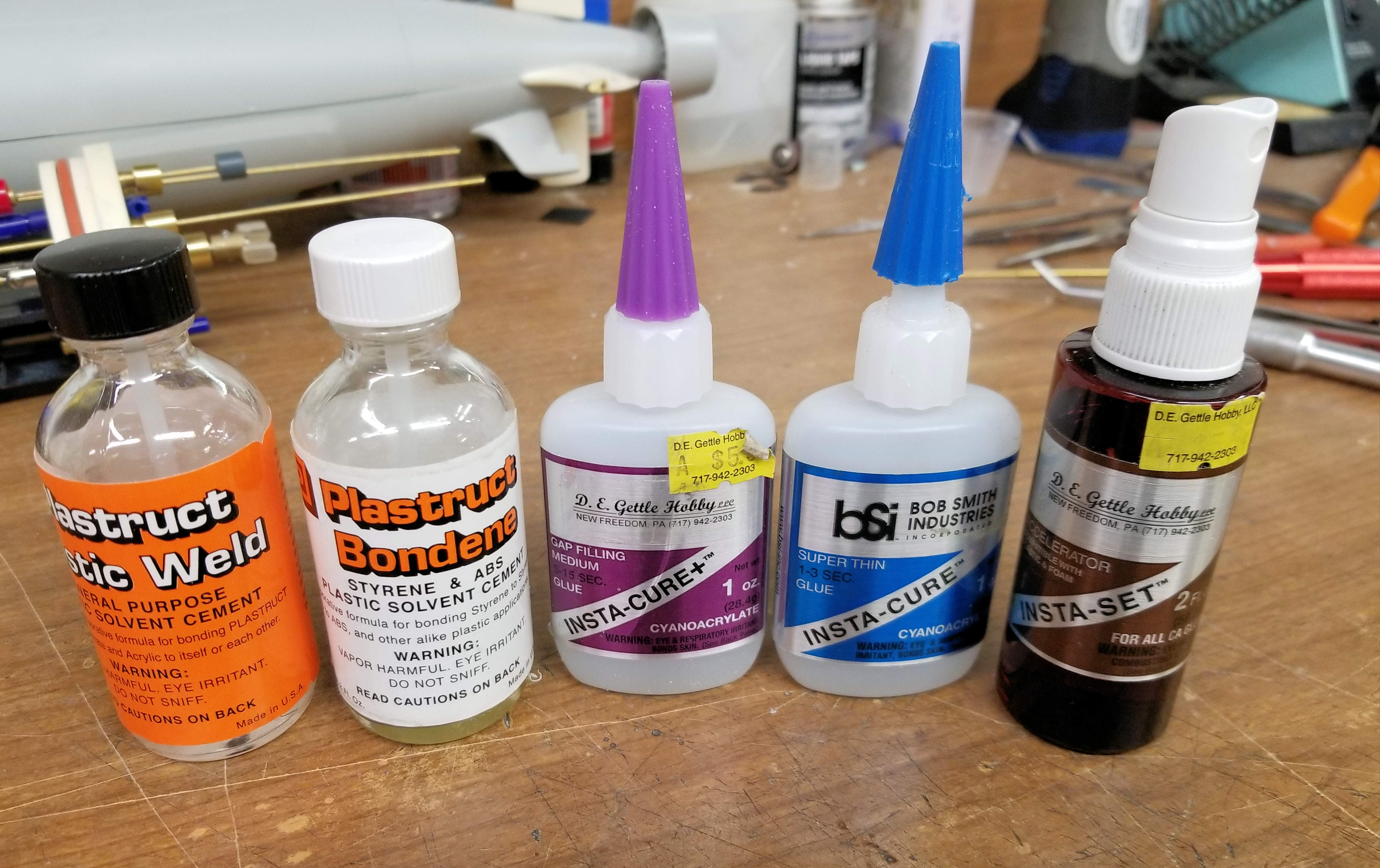
Let’s take a couple minutes to identify a few items that you’ll need to complete this build. First off, adhesives. From left to right:

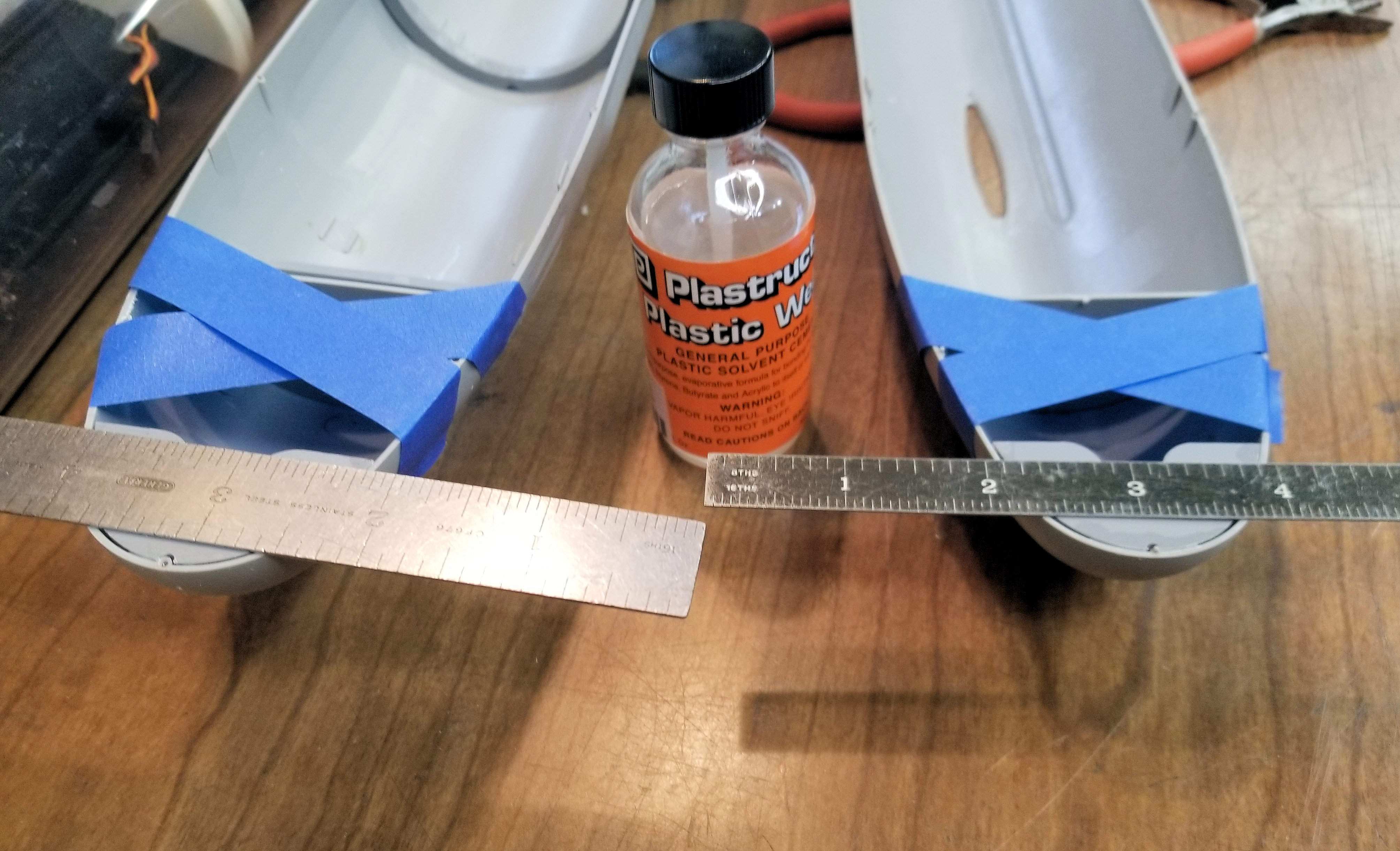
1. Plastruct Plastic Weld cement. This is a general purpose solvent cement used to join dissimilar plastics to each other. This is a necessity for bonding the R&R supplied plastic parts to the Trumpeter styrene parts.

2. Plastruct Bondene. This is a fast acting solvent cement used for joining similar plastics, especially styrene and ABS.It makes quick work of joining the Trumpeter parts to each other.

3. Medium viscosity CA glue, aka “superglue”.Sticks most anything to anything else, especially fingers. The difference between cement and glue is this: glue adheres things to other things by the adhesive properties in it, while cement actually slightly “melts” the items and forms a molecular bond.

4. Super Thin viscosity CA glue.As above, but much thinner.

5. CA accelerator.Used to speed up the solidifying of the CA glues.

And, some necessary tools, from top to bottom.

1. Hobby knife.Don’t forget to have lots of extra blades on hand.

2.An extended reach hex driver.You’ll need this to get back into the stern to tighten the linkage setscrews.The 2 most needed are .05 SAE and 1.5 mm.

3. A set of miniature files.

4.I couldn’t find an extended.05 hex driver locally, so made one by cutting the short leg off a regular Allen key and chucking it in a pin vise.

Not shown but most helpful is a hobby moto-tool (Dremel or similar) and a set of cutting bits, including carbide cut-off wheels. 


And with that, let’s get started!

Carefully remove all the hull parts from the sprues. Cement all 3 pieces making up the bottom half of the hull together. The parts key into each other fairly well, just make sure that you have them in the right place and glue. Here’s the bow section joint.

Once this is done, you’ll need to cut out the bulkhead at the joint of the lower mid section and the lower stern section.

leave a small bit of the bulkhead in place as a guide for the prop shaft bulkhead to be installed. You want the lower rear bulkhead joint to be like the photo below of the upper bow bulkhead.

Cut out the centre of the stern hull section as shown for passage of the prop shaft.

Next, cut out the centre of the propulsor inlet side vanes, This is the only part of the propulsor that we’ll be using except the shroud, the flat prop and outlet vanes will be discarded.The inlet vane assembly will house the R&R supplied prop shaft bearing which is in a cast resin housing.

Once the vane assemble is cut out, you can assemble the stern cone.  I’m certain that there are multiple ways to do this and get the prop shaft alignment correct, here’s how I did it.  I put the bearing and bell crank support in place against the hull bulkhead (remember, the one I told you 

Next, tape the upper stern hull section in place. You can then put the prop shaft, rear prop shaft bearing, and propulsor vanes in place and hold them there. Once everything is fitting properly, carefully cement the bottom of the vanes to the lower hull. DO NOT get any cement on the upper hull / vane joint.

When the cement has set, remove the upper hull section. This will leave the lower hull, vane and bearing assembly, prop shaft / bell crank support, and prop shaft in perfect alignment. Carefully finish cementing the parts together.

When you remove the prop shaft you’ll have the shaft bearing held in place by the propulsor vanes. This is done to allow for just a bit of float in the bearing housing to allow for any minor misalignment.

Time to move on to the Rudder and Dive Planes

You may now cement the stern section of the upper hull to the lower hull assembly. Ensure you have it properly aligned, tape in place, then apply cement.

The rudders and planes have 2mm stainless steel shafts cast into place, so we’ll need to drill holes in the hull for them. Use a #46 drill bit, which is just a tiny bit larger than the shafts.

Next is to prep the control surfaces for fitment. The rudders are easy, they’re one piece. The dive planes consist of the moving surface and a “lead-in” fairing called a stabiliser which does not move but is fixed solidly to the hull. Make sure that there is no flash in the joint which would cause binding. If there is the tiniest bit,  it is easily cleaned up with the round file. In order to allow clearance for the plane to rotate, put a couple pieces of masking tape on the leading edge of the plane. Then tape the two pieces together as shown below. Now you can use them to locate the pivot holes to be drilled.

This step requires close attention.  Because the new planes are functional, the shaft pivot hole is at a different spot than the ‘location pin” cast into the kit dive planes. 

DO NOT DRILL THE DIVE PLANE SHAFT HOLES IN THE HULL AT THE KIT LOCATION POINTS!

The upper and lower rudder shaft holes are simple, they need to be drilled exactly where the kit location holes are.  Remember to hold your drill vertical, and not perpendicular to the hull surface.  By holding the dive planes against the side of the hull and matching them up with the raised cast surfaces on the hull you can see where to drill the shaft holes. The correct location is about 4mm to the rear of the kit hole.  Again, make certain to drill perpendicular to the hull centerline, not the side of the hull.

Time to spend a little time making sure that the dive plane stabilizers fit the pads on the sides of the hull correctly.  Once you have the dive plane stabilizers fitted square and true, go ahead and glue them to the hull.  You’ll use the medium CA here to help fill any gaps that may exist.

Okay, now we’re getting serious. Use the masking tape to tape the dive planes in location with the stabilisers which are glued to the hull.  Working inside the hull, fit the control arms to the shafts, and take note how much of the rudder shaft protrudes from the arm. This will need to be trimmed as close to flush as possible on the port (left) side of the boat. The starboard (right) side one isn’t quite as critical, but still has to be short enough to not contact the prop shaft. Remove the control arms, remove the dive planes, and trim the shafts to the required length. Once trimmed, reinstall the dive planes.

Back on the outside of the hull we’ll need to make an outer dive plane shaft support for each side of the boat. Shape a small piece of brass to follow the contour of the dive plane fairing and front part of the plane itself. Drill a small hole the same size as the one you drilled in the hull in the brass support plate. Spend some time with the files getting all the edges of the fairing, plane, and support fitting well, then CA the shaft support plate to just the fairing. This supports the planes at both ends and keeps them from flopping around.

At this point  remove the push rod bell cranks to allow easier access for fingers to work in the stern. It’s tight in there.

With the dive plane push rods and control arms installed, we can turn to the rudder installation.  First verify that the upper and lower rudder shafts don’t hit the propshaft.  Slide the rudder yoke onto the upper rudder shaft and get it centered as closely as possible in the hull. Slide the lower rudder into the yoke to get things in line. If the yoke winds up too high the pushrod will hit the dive plane control arm, too low and the pushrod will hit the side of the hull.  It’s finicky, but does fit.  You’ll be thanking me now for those extended reach hex drivers.


Once the WTC is fitted, the push rod will need to hook up near the top of the hull. So, before you fit the rudder push rod for the final time, put a “Z” bend in it so that it exits the stern section at the top as shown below:

Reinstall the pushrod bellcrank and run the dive plane pushrods into the pivots.If you’ve taken your time and got it all lined up, it should look like this. 

Hey, we’re starting to look like something here now!Take a big breath, grab a cold one, relax and enjoy the view of your handiwork.The tough bit is behind you!

Thread the propeller onto the end of the prop shaft and install it in the hull from the stern. There is no lock nut behind the prop. It’s quite possible that the shaft won’t fully enter the hull because of the threads. When the threads are formed they can sometimes leave a ridge at the point on the shaft where they end.If that is the case, lightly dress the ridge with your motor tool or file until it goes into the bearing. Once the prop shaft is installed, put the drive yoke on it and snug up the setscrews. Make sure to leave enough end play that the shaft turns easily. 

Fit the cylinder support saddles (the parts with hooks for rubber bands to hold the cylinder in place) in the hull. The aft one goes just behind the small hull alignment tabs in the lower hull.  The forward saddle locates just in front of the hull alignment tabs towards the bow. The location is not critical, but they fit well in these locations. Once fitted, cement them in place with several applications of the Plastic Weld cement. Let dry thoroughly.

Place the cylinder in the saddles in it’s approximate location. Slide it fore and aft until the drive yoke on the rear of the cylinder aligns with the drive yoke on the prop shaft as shown. You want the yokes to overlap most of the distance of the “legs”. Once you have the location fore and aft, make absolutely certain that the cylinder is sitting straight up in the hull so that the output shaft is centred.

Slide the rear cylinder locating plate into position up against the rear of the cylinder. Note that the plate has a slot in it which the inlet for the ballast system fits into. With the locating plate held against the rear end cap of the cylinder, use a couple drops of Plastic Weld cement to glue it to the hull. Once the cement has set, remove the cylinder and fully cement the plate in place from both sides. 

Put the cylinder back in the hull, locating it with the rear plate. Once in position, place the front cylinder locating plate in the lower hull and cement in place as you did with the rear one. With both locating plates glued into position the cylinder is held between them and cannot shift in the hull.

Now it’s time to install the bow magnetic joining plates. Use a steel rule to hold the plate flush with the hull split line on both the top and bottom halves. The plates may not fit the hull shape exactly., Use a bit of masking tape to help convince the hull sides to pull in enough to touch the plates. Once tacked in place with the Plastic Weld cement,  I stood the hull halves up and filled the gaps from the inside with slow curing epoxy. Do not use “5 minute” epoxy, as it will soften with repeated exposure to water. Once the magnet plates are installed and cured, they hold the hull halves together securely.

Cut a slot in the upper hull just smaller than the base of the sail. This is very important to not trap air inside the hull when diving

Assemble the 3 pieces of the sail with the Bondene cement. Clean off any flash.I cut away the bottom and forward wall of the cockpit to allow air to freely escape. Also, drill a small hole in the rear upper corner of the sail, again to allow air to escape while diving.

Do not glue the sail to the upper hull yet.


At this time you’ll need to fit out the dive cylinder with your electronics and make it ready to install in the hull.

You’ll need to install:

  1. A receiver on a frequency appropriate to your location.
  2. An electronic speed control for the drive motor
  3. An electronic speed control for the water pump motor
  4. A missing pulse fail safe to actuate the pump if radio control is lost.
  5. A 6 cell, 7.2v Ni MH battery
  6. Optional, but recommended - a pitch controller (auto leveller)

Below are some photos of my installation. Yours may (will) be different based on your choice of equipment. I used m Troniks speed controls due to their size, a Novak receiver, and an Ofna failsafe. 

The battery fits perfectly in the lower forward cylinder compartment. Run the positive lead rearward to the power switch, and then back to the speed control power inputs. Plug both speed controls into the receiver. ENSURE THAT YOU REMOVE THE RED LEAD FROM ONE OF THE SPEED CONTROL TO RECEIVER PLUGS. Only one speed control should be feeding power to the receiver.In the below pic I have removed the red lead from one speed control, and insulated it to prevent it from shorting anything.

Connect the speed control outputs to the pump motor and drive motor terminals. Plug the 2 supplied servos into the receiver and verify that everything works as planned. The ballast pump draws water thru the inlet at the bottom rear of the cylinder and fills the tank to the horizontal plate inside.Air is vented out of the top of the tank through the hose leading to the top rear end cap. The outside of this fitting will be connected to a “snorkel” vacuum break later on.

Drill the next to outermost holes in the servo arms large enough for a snug fit to the push rods. Make “Z” bends in the push rods and fit them to the servo arms.Ideally the push rods should exit the O-ring seals parallel to the centre line of the cylinder, with minimal side to side movement. The better this alignment is the less chance there is of leakage.

The push rods will need to be cut to length once fitted. With the servo arms turned so that the push rods are retracted into the cylinder as far as they can go, cut the push rods so that enough protrudes from the seal housing to fit the magnetic connectors.This is about 10 mm from the housing.

With the cylinder in place in the hull, fit the magnetic connectors to the push rods, thereby connecting the cylinder push rods to the push rods leading to the rudder and dive planes.  The rudder push rod connects directly.  The dive plane push rod needs an intermediate rod from the connector to the control yoke.  I found that the easiest connection was to bend the intermediate rod in a “U” shape and connect it in that manner.

Once that you have verified that everything functions as expected, rudder and dive planes operate without binding,

drive motor and ballast pump operate, it’s time to finish up the outer hull.

We’ll begin with the lower hull. With the dive cylinder removed, locate the flood holes which you’ll need to open for water ingress. Carefully drill them thru with a small twist drill then file to get the final shape. Thankfully the styrene works easily.I started with the holes as you see, but you can always open more if necessary.

On the upper hull I drilled holes in the locations where the rearward 4 cleats are meant to locate.Hopefully these and the openings on the sail will be sufficient for air to escape.

Inside the upper hull I opened up a large “window” in the bulkhead where the bow cone is glued to the main hull.  This will allow air to escape the bow freely and travel to the sail to exit. 

Fit the vacuum break snorkel head inside the sail, and secure it with a couple drops of CA. Then the sail is glued to the upper hull with the tubing from the snorkel head leading thru the slot in the upper hull. This will be connected to the vent port at the top rear of the dive module.

And with that, we’re ready to head to the test tank to check for water tightness, and begin the trimming out process.