Aquabat Building Instructions. The instructions here  are to complement the building instructions supplied with the kit.

The first step is to cut out the access hole, keep the modded bead around the edge, it helps strengthen the flange.


Using the clear plastic cover as a template drill out the 10 holes to 5/32” dia, pop the screws in as you go just to prevent it moving around.

Once the flange reinforcement strips are secured then drill through the 5/32” holes and increase to 5mm dia. Place the rubber cap and plastic top hat over switch hole and secure with superglue.

Pop all the screws into their holes and tighten up loosely, this expands the brass inserts into the plastic.


Mark out the positions of the securing cleats on the inside of the upper pressure hull moulding and drill out to 3/32” dia (2.4mm) then just lightly countersink the outside with a larger drill bit(3/8” ish)Push the plastic cleats through the holes and melt over the other side with a hot screwdriver blade. Once melted over run a little superglue around to ensure that they are secure and water tight.


Mark out some equi spaced hole positions (I put 9) and drill through about 1/4” dia (6mm) these are for the baffle plate through the centre of the ballast tank. Once drilled then lightly countersink both sides to ensure a clean hole.

Drill out the internal ballast tank half ( the one with the nipple moulded in) for the pipe connection with a 13/64 dia hole, then glue the blue pipe connection into the hole. Ensure that it is glued securely using a good quality plastic glue (devcon plastic 

https://www.facebook.com/178229909182706/videos/57...


Drill a 6mm dia hole in the top of the upper deck moulding just behind the glass dome position (make sure that it clears the dome when attached. Position the upper ballast tank half and line it up with the hole. (This can be a bit tricky so take your time)welder or similar)

Once your happy with the position then you can secure in position with liquid plastic cement. Re-check the position before the glue sets and you can slide it around a little by poking a small screw driver blade through the hole if necessary. 

Finally secure the ballast tank in position.

You now need to ensure that the tank is airtight, I used some medium thick superglue and let it run all round the joint, I needed to help it round a little using a coffee stirrer, and finally curing the glue with activator.

Now repeat the procedure with the upper ballast tank half and align the water inlet tube with the water pump location.

https://www.facebook.com/178229909182706/videos/57. 

https://www.facebook.com/178229909182706/videos/57.

https://www.facebook.com/178229909182706/videos/57...


I’m going to carry on now after a bit of a break waiting for you guys to catch up. Put the lower nozzle ring support rod in place through the 10mm hole leaving around 30-35mm sticking out. Tack in place with a spot of superglue and then cover over with a good quality epoxy that is suitable for plastics. It is vital that this joint is water tight.


Next step is to drill a 5mm dia hole to take the water inlet/outlet pipe. Push the moulded outlet pipe, tack in place with a spot of superglue and finally secure with a good quality epoxy that is suitable for plastic.


Now we need to cut out the push rod exit guides. Cut roughly to the line shown here using a hacksaw or similar, leave a little over for safety and then drill a 6mm hole through to take the rubber bellows.


The next step is to sand the exit guides down to shape, wrap some sand paper around a piece of tube about 3” dia and away you go, keep sanding until the pencil mark is sanded off and that’s enough.

https://www.facebook.com/178229909182706/videos/57...

The finished guides can now be secured to the hull, it is vital that these are fitted securely and are watertight. To achieve this I fix them with thick superglue spread carefully in a continuous bead around the mating surface, once cured I then carefully go round the outside edge and seal up any gaps.

Finally drill right through into the pressure hull with a 6mm drill, take your time and take it steady to ensure that you don’t split or break any of the mouldings, you don’t want the drill bit to suddenly grab. If you are in any doubt then start with a smaller drill and work your way up to 6mm.


We can now put the upper and lower halves of the pressure hull together. Us contact adhesive along the mating surfaces, spread it on and smooth it out on both surfaces, leave for a few minutes until just about touch dry and the push the two halves together firmly and clamp into place using clamps, elastic bands, clothes pegs or pretty much anything that will hold. Leave for at least 6 hours to set.


Now that the pressure hull is assembled the next step is to make sure that it is water tight. I have used evo-stick product called “Sticks like Sh*t” and believe me it really does. Don’t get this on your fingers, it’s difficult to get off. Build up in several layers to fill the gap around the joint. I find it better and less messy to push the gun rather than draw it but simply make sure that it is all pushed down inside the joint and there are no gaps or holes and all should be fine.


You now need to drill the 3/8” dia hole through the stern for the prop tube. Take it easy here and build up to 3/8 by steps in drill size, you don’t want to rip the mouldings.


Next step is to put the motor and prop shaft assembly together, remove the screw on stuffing box and “0” ring so that it ca be passed through the 3/8” dia hole. Cut a piece of the spare gasket sponge just long enough to go round half the motor diameter.

Slide the prop tube assy through from the inside, screw the stuffing box back together. Pop the kort nozzle and support ring onto the lower support and check that the prop is close to centre of the nozzle. Don’t worry too much if it’s a little off centre, you can clip a bit off the edge of the prop blades if necessary. Tack the prop tube into the hull with a spot of superglue. Just enough to keep it into position is all that’s needed, the next step is the important one.


This part of the assembly is quite tricky and VERY important. 
Remove the motor, shaft,stuffing box and seal and tape over the prop tube thread ( to prevent any glue getting on it ) Next mix up some epoxy glue (it’s worth getting the glue warm before mixing so that it thins out and flows easily) Next carefully pour the glue so that it surrounds the prop tube boss inside. It’s vital that you get the glue into all the nooks and crannies to ensure water tightness. 
I have found from experience that this is the most common place for a leak so a few xtra minutes here will save a load of heartache later. Make sure you don’t get any glue down the shaft hole but if you do then a 4mm drill should clear it.


Reassemble the motor and shaft assembly and pop the whole lot back inside and secure with an elastic band, secure the pump on its mount and again secure with an elastic and then pipe up, as shown on the drawings supplied with the model. 


The next  thing to do is cut and attach the lid gasket to the apperture. Carefully stick the gasket over the access hole and cut out the middle. Take care here, you will need a really sharp blade to make a tidy job and keep the middle piece and place it back onto the backing paper, we will need this later.


Once that part is completed we need to find out if the pressure hull is watertight. 

Replace and secure the Perspex cover and gently tighten down. A smear of Vaseline over the surface of the gasket will show the cover sealing up as it is tightened and help prevent damage to the flange and cover.


Right, we've now got to check for water tightness, in the first instance the easy thing to do is simply blow into the access hole and listen out for air escaping. If you do hear something try to trace where it is coming from and seal it up but if it is difficult to find then push a piece of tube carefully up inside one of the rubber bellows and attach a piece of tube, then lower the boat under water in your bath or whatever and look for bubbles when you blow into the tube. This should easily identify any problem points. If there are bubbles coming out of the water inlet pipe then you have a leak on the ballast tank somewhere. Once all is well and you are happy that all is watertight then we are good to go with finishing of the model.

Ok, we’ve got the pressure hull assembled and water tight, the motor is in and so is the pump so the structural part of the boat is pretty much finished. The rest of the assembly is fairly straight forward. Take the two haves of the ballast containers and glue them together, use a couple of elastic bands to hold them and work your way around the seam with glue ( I use liquid poly). Glue on one end cap and cut the other end open.


The next step is to simply fill the tubes with water and see if it runs out, we need these ballast containers water tight because any water that leaks in will upset the trim of the boat and could even prevent you surfacing. An easy way to do this is simply run some thin superglue around the inside but mind your fingers.
Once done and secure then we need to fill up the tubes with lead shot, we are trying to get around 2lbs in there so the smaller the shot dia then the more you will get in. Mine weigh 960 grams each and the boat carries 2 x 7.2v x 3.3 ah batteries.
You can attach the end cap with waterproof sticky tape until you are happy with the weight and trim of your finished model.

The ballast holders are the next job, it’s a good idea to mark a line to show where you need to go. Cut them out roughly using a hacksaw blade or whatever comes to hand. Leave a bit of material above the line for safety

Next we need to bring them close to finished size, I find a Dremel with a coarse sander really effective but sandpaper will do a good job by hand and less likely to take too much off.

https://www.facebook.com/178229909182706/videos/60...

Finally we need to finish them off to size, I used a Stanley knife blade for this but mind your fingers. Just keep scraping until the line starts to disappear. I confess at this point that Stephen Spielberg has nothing to worry about.

https://www.facebook.com/178229909182706/videos/60...

Once you have the side mouldings cut and sanded to shape you will need to drill a couple of holes through for the tie wraps used to secure the weights. Once that job is done then the holders can be glued on to the hull. Positioning is not too critical because we can slide the weights back and forth.


We are almost there now, we move our attentions to the upper deck moulding and drill out the flooding holes, the size and pattern is entirely up to you and your desire to make your model a bit different. I have used only the holes marked and drilled 4mm at the lower end, 3mm for the middle row and 2mm for the air holes across the upper surface. We need to carefully drill a 10mm hole for the upper nozzle support bar and a slot to accommodate the prop stuffing box, all as shown here.


Put the top and bottom hull halves together but don’t glue just yet, and pop the upper nozzle support bar loosely into place. Assemble the nozzle and support assembly and put in place so as to line up the top bar. Tack into place with a little super glue then remove the nozzle, remove the top and secure the rod in place with some plastic epoxy as the lower one.

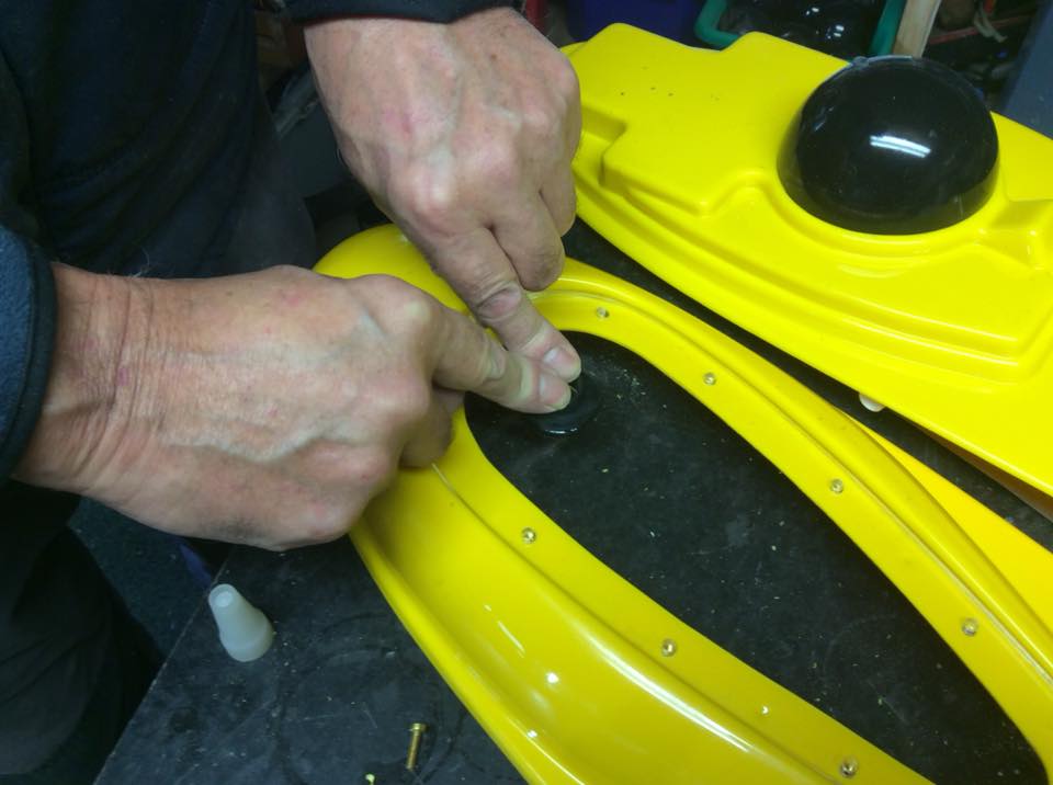
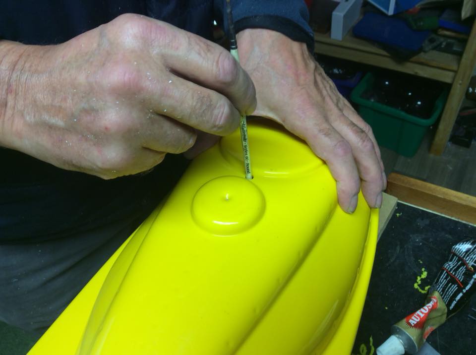
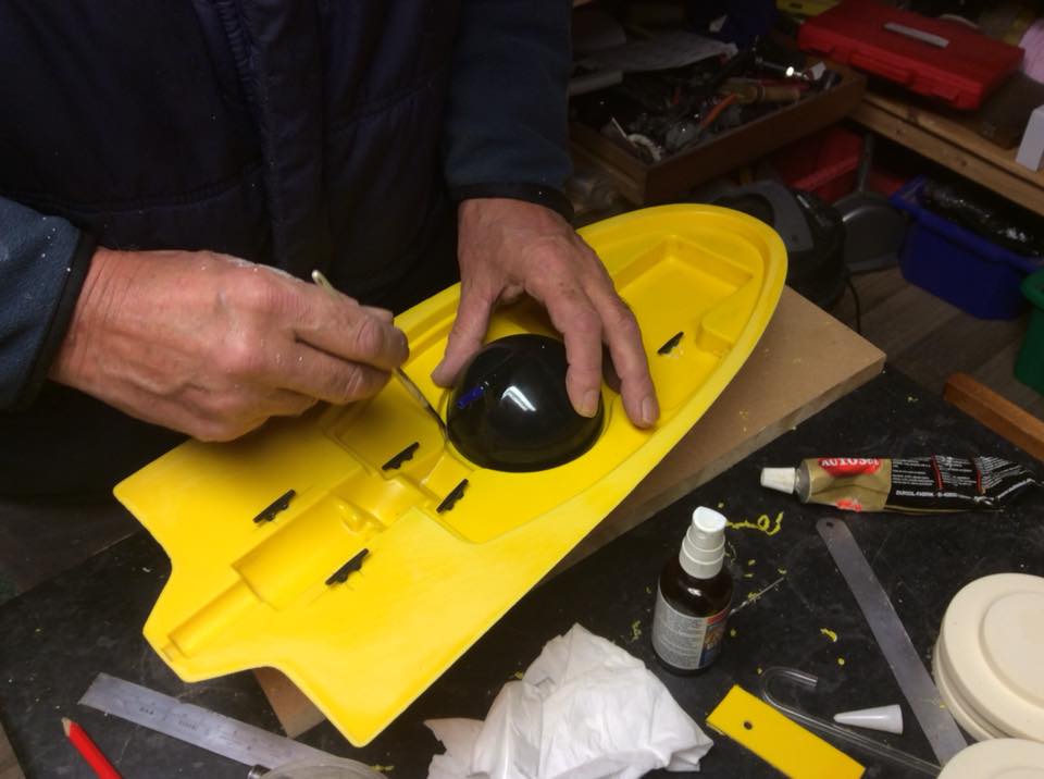
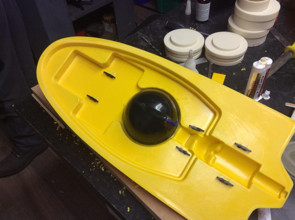
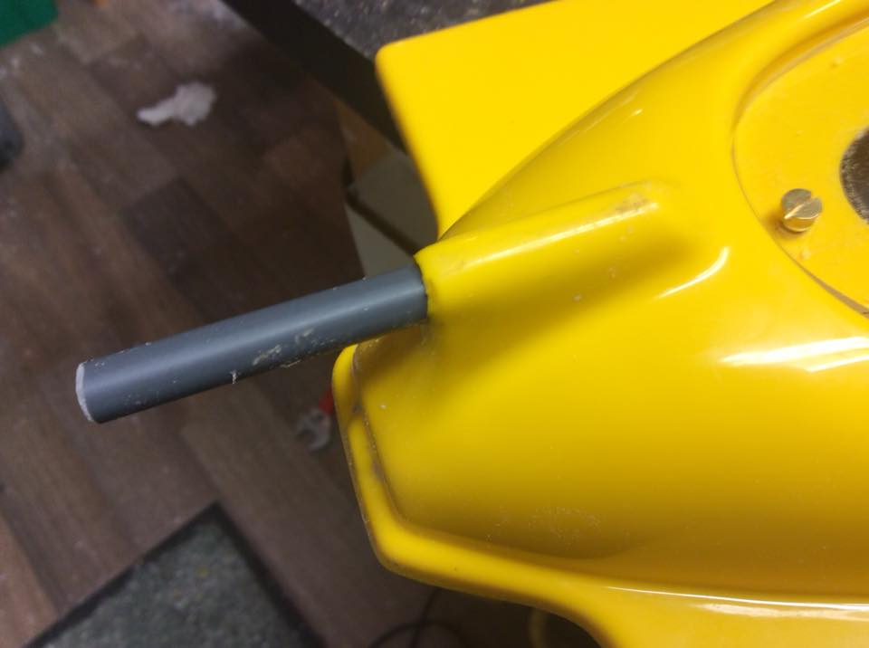
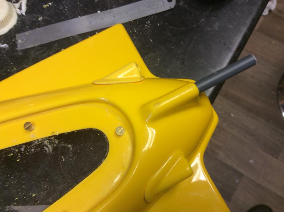
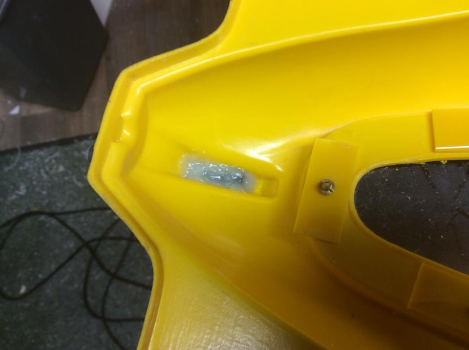
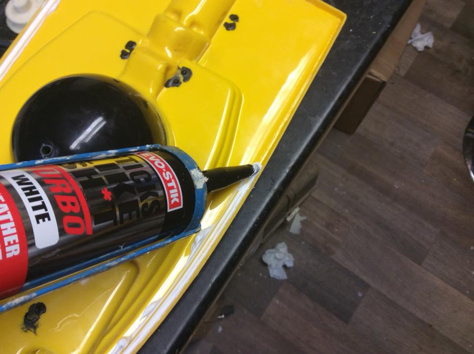
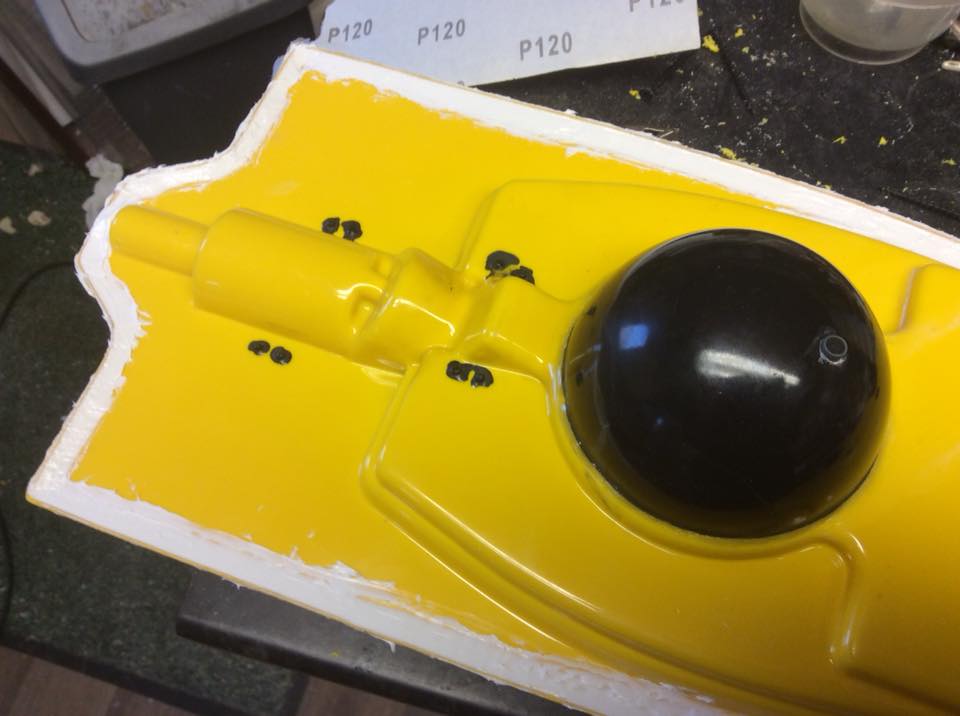
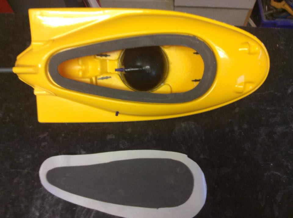
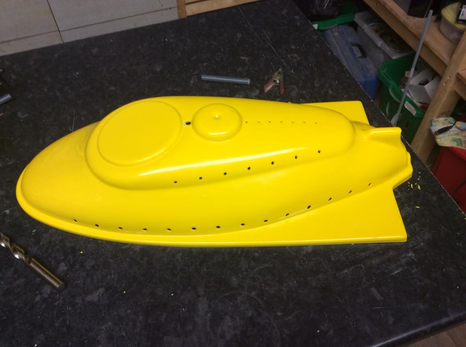
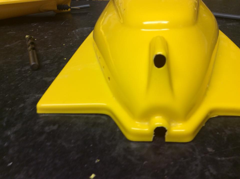
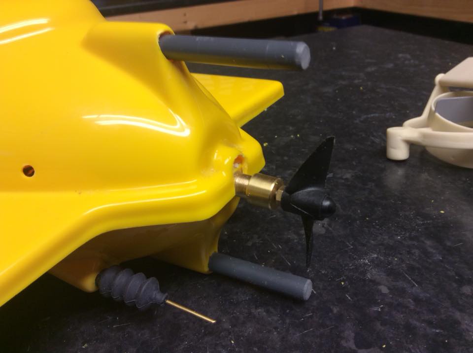
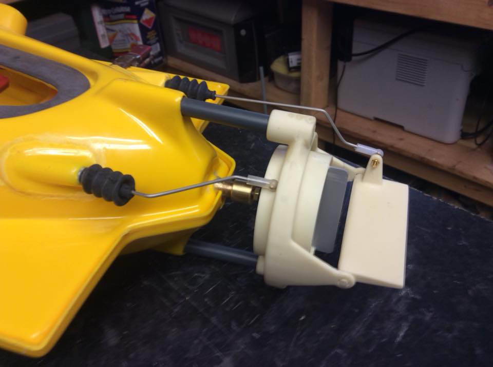
I’m almost on the last leg, next thing to do is assemble the top and bottom hull halves and clamp together, then pop the nozzle assy in place, there is no need to glue this as it is a press fit onto the pvc rods provided and if glued in place it will prevent you separating the hull halves in the future if needed. Now glue the top and bottom halves together with some ordinary 5min epoxy. I use this because,in fact, it will not bond to plastic very well but it holds well enough for our purposes. If you install any lighting,cameras etc you may need to get into the space between the hulls and by using 5min epoxy the halves can be easily cracked apart without any damage.

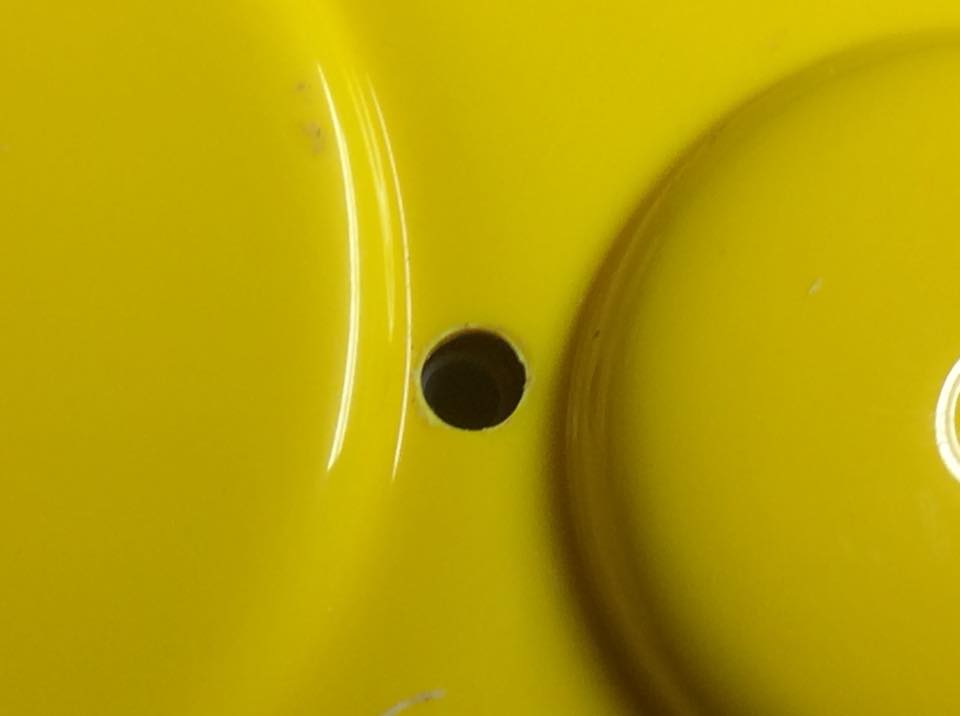
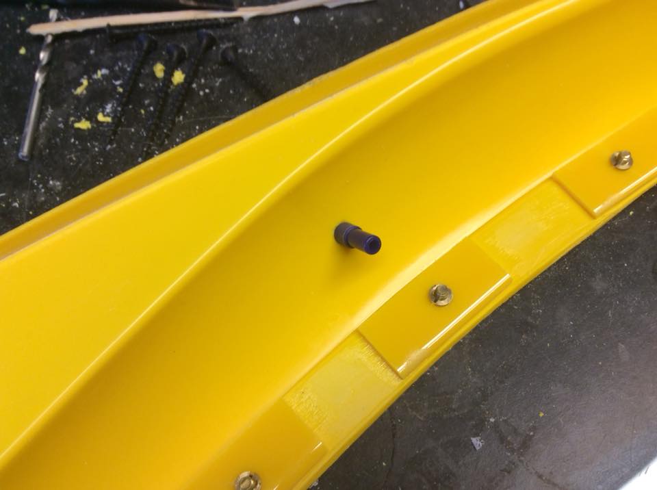
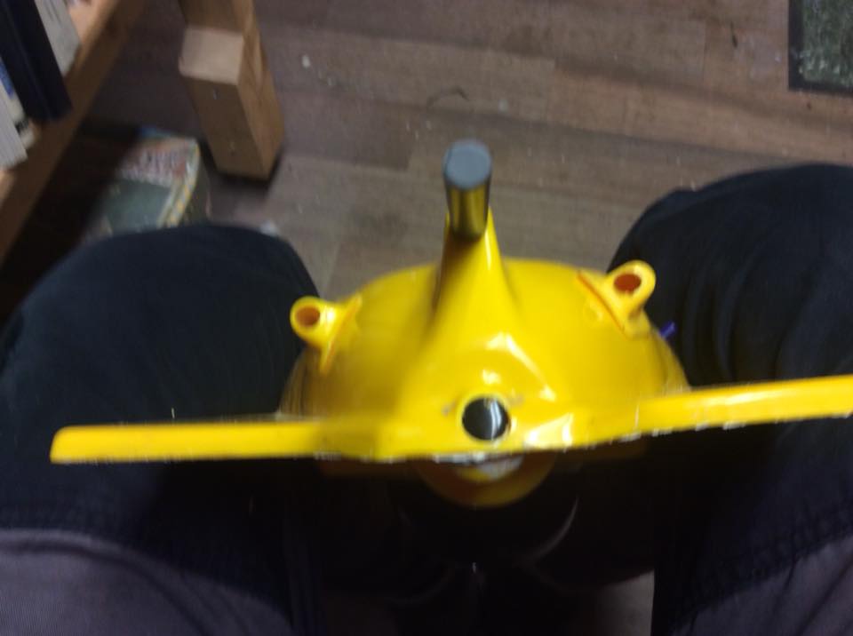
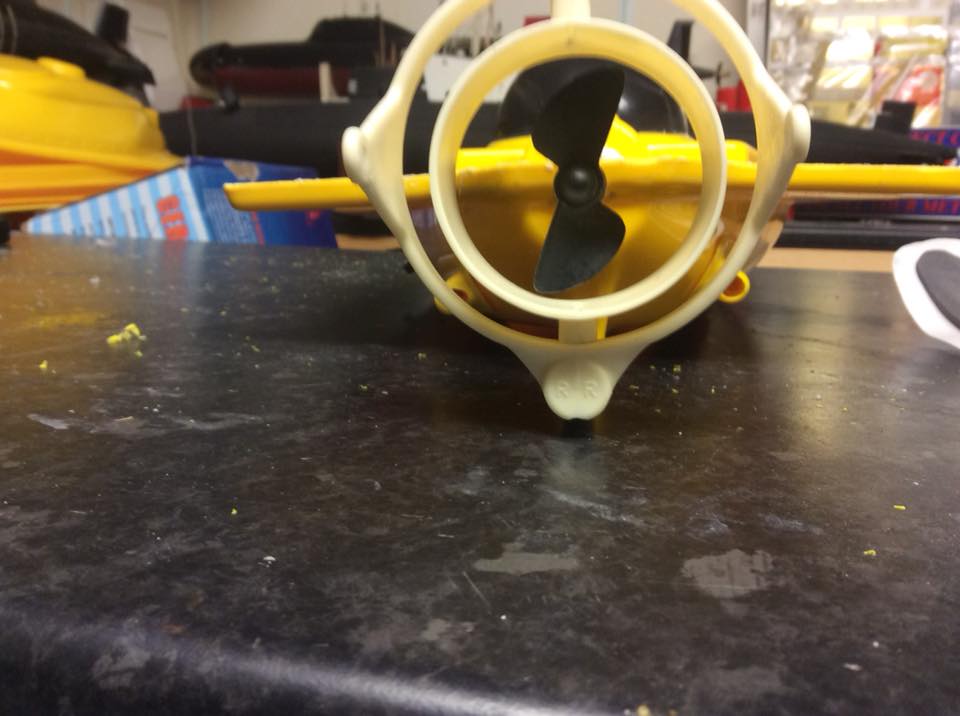
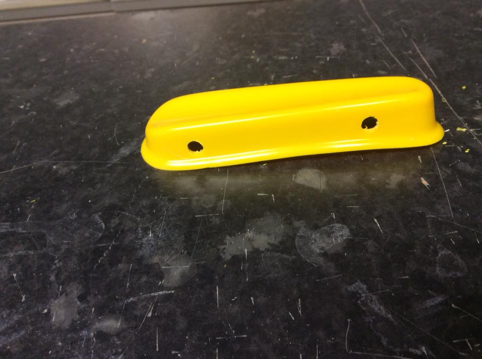
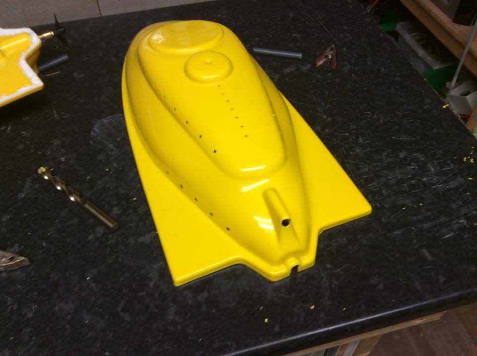
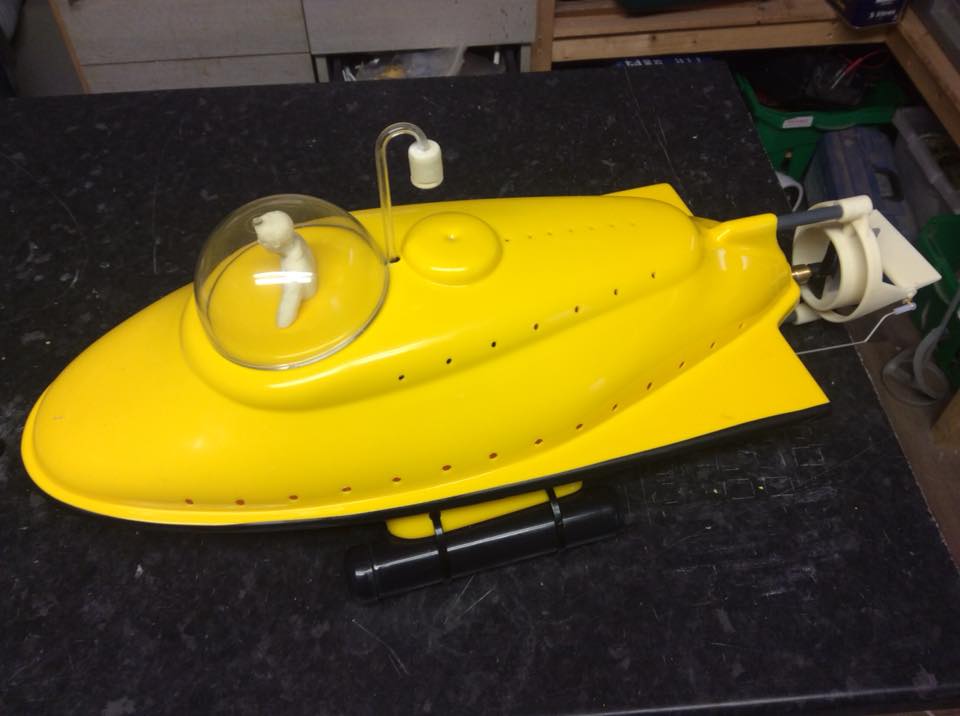
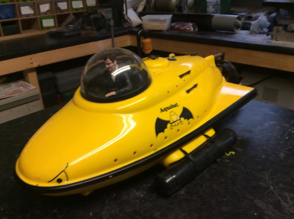
Once the top and lower hull halves are glued together I usually cover over the joint with some electrical insulation tape, it tidies things up nicely and is cheap and easy to get. It also acts as a bumper to help prevent scratching. Last step is to pop the snorkel in, fit your radio control and all is done. We have supplied some fittings to tart your Aquabat up a little and place these where you most like the look of them, you can see my old Bat (now over 20 years old) to give you some ideas.

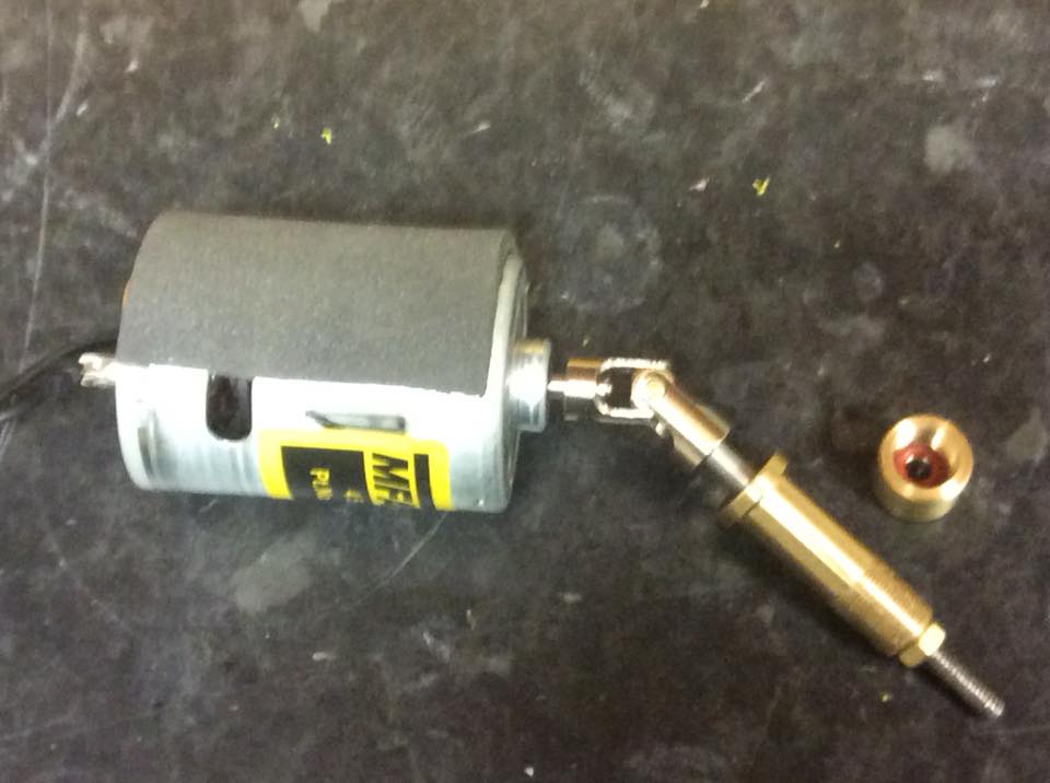
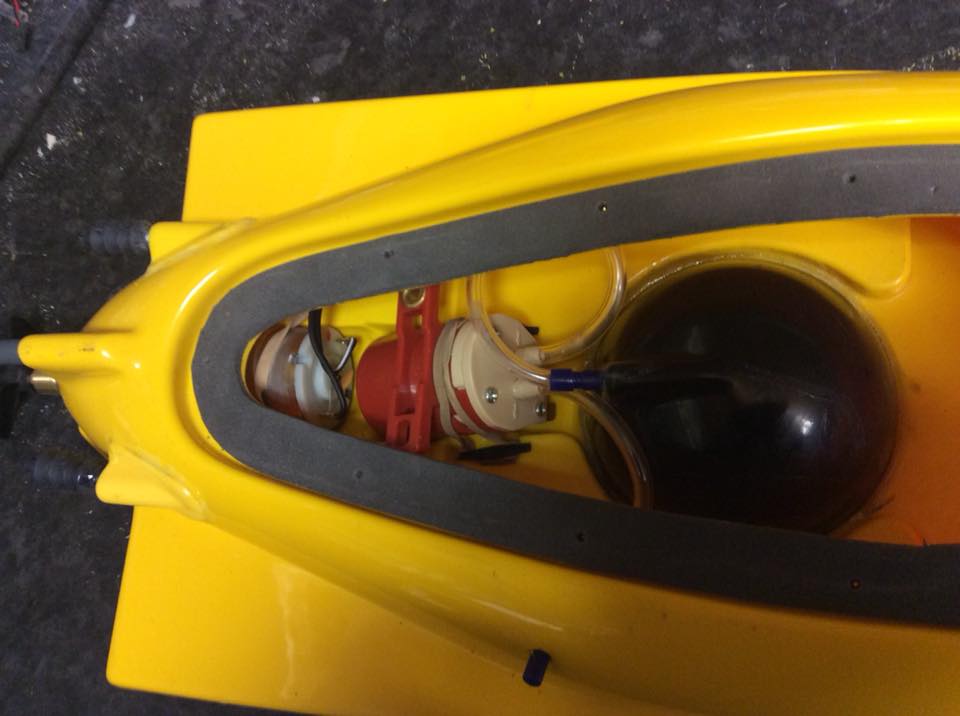
I hope these hints and tips have been useful to those currently building an Aquabat or those presently considering purchase. The drawings included with the kit should make installation of equipment straight forward but just a point here, some owners have found using an additional speed controller to operate the water pump advantageous. If you go down this route then you must disconnect the red (positive) lead on the drive motor speed controller leaving the bec on the pump controller so that an in line failsafe can be used.

To finalise, a few notes on trimming. Pop the boat in the water and fill the ballast tank (when water spurts out of the snorkel then the tank is full, you can adjust the amount of water taken on by sliding the snorkel in or out) Once the tank is full then slide the weights back and forth to achieve an even keel. You may need to add additional weight inside to get the boat to the correct level but it will not be much. The correct level is with just the top of the dome breaking surface. It really is that simple.Off you go and have fun but look out for surface craft, they will almost certainly not see you. One last thing, thank you for purchasing our Aquabat, we wish many hours of enjoyment sailing it.